Visualizing Quaternions: Belt-Trick Documentation


Back to Home page.

 
Overview Description Download Using the Application Application Interface
  • What is the Belt Trick?
  • Snapshots of the
    • Demonstrations
    • Interface
  • Platforms supported
  • Download links for
    • License
    • Executables
    • Source Code


I. Overview

1. What is the Belt-Trick?

A popular physical demonstration, called the 'Belt-Trick', employs an ordinary belt to showcase the properties of the Rotation-Group. This demonstration involves a flat, elastic ribbon or a flexible belt whose ends are fixed after an initial twist. It is observed that with some manipulation, and without cutting the belt or detaching the ends, a doubly twisted belt can be straightened out, whereas a belt with a single twist cannot be untwisted (see figures below).

This elegant demonstration immediately elicits a 'why' on the part of most observers. While the demonstration is straight forward in clarifying the 'how', it falls short in providing the information as to why only the doubly-twisted belt untwists. The complete explanation becomes evident only after indulging briefly into the properties of three-dimensional rotations and their alternate, four-dimensional avatars, in the form of the mathematical entities, called quaternions.

The application provides a graphical simulation of the belt-trick and provides a visual explanation of the properties of the phenomena using quaternions.

2. Snapshots of the Demonstrations

The following images show the stages in the trick for a belt, which has been twisted once (a) and twisted twice (b)

a) Sequence of figures showing the belt transformations for the 360° or single-twist configuration:-

 Belt-Trick sequence for 360-degree case

b) Sequence of figures showing the belt transformations for the 720° or double-twist configuration:-

Belt-Trick sequence for 720-degree case

This document contains usage of the application that demonstrates the belt-trick. The features and terms occurring in the application are explained along with some screen shots of the interface.  A brief description of the belt-trick is provided in the section below.

3. Snapshots of the Interface

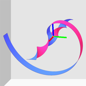
Snapshot 1: View of the belt being deformed Snapshot 2: View of Quaternion-curve corresponding to the orientations of the belt-segments

top


II. Description

1. Introduction:

The 'Belt-Trick' visualizes the nature of the group of rotations (or the Group SO(3)) in three-dimensional space. One of the unique and interesting properties of this group is that a belt with two twists and fixed ends can be continuously deformed into a straight and untwisted belt. The same, however, is not true for a belt with only one twist.

This striking phenomena can be demonstrated by using any ordinary belt. However, the physical demonstration lacks sufficient information which is necessary to completely characterize the behavior of the belt. This shortcoming of the physical demonstration is overcome by using graphical visualization of the phenomena. The visualization allows not only the manipulation of the belt-deformation, but also displays the relevant information from a unique perspective that is entirely missing in the physical counterpart of the trick.

2. Using Quaternions to Describe Belt-Trick:

The unique perspective is provided by employing Quaternions to visualize the intriguing phenomena of the belt-trick. Quaternions are vectors in four-dimensional Euclidean space (R4) and unit-quaternions represent orientations in the lower, three-dimensional space. An orientation can be thought of as a triad of three, mutually perpendicular axes, with one axis along the fixed axis of rotation.

Quaternions are used in this manner to represent orientations of the segments on the belt, which lie adjacent to one another along the length of the belt. Since quaternions are four-dimensional vectors (think quaternion, q = (w, x, y, z), where w, x, y, z ε R, real-numbers), they are visualized by projecting the three out-of-the-four components of each quaternion into the three-dimensional subspace. A visualization of the quaternions is called the quaternion-map (more on quaternion-map here).

Once each segment-orientation has been captured by a corresponding quaternion, the series of quaternions are connected to obtain a connected curve in the four-dimensional space, which we call the quaternion-curve. The behavior of this quaternion-curve, during belt deformation, then provides an insight into why only a doubly-twisted belt straightens out.

3. Properties of Quaternion-Curve:

The quaternions for the belt-segments are displayed as beads on the continuous quaternion-curve. Each bead corresponds to the orientation of a single belt-segment. Interestingly, the correspondence between quaternions and orientations in three-dimensional space is a 2:1 mapping. This mapping implies that each orientation in the three-dimensional space is represented by two quaternions in the quaternion-space. This pair of quaternions lie diametrically opposite on the unit four-dimensional sphere (or the hyper-sphere). The two-to-one mapping, also know as the 'double cover', has significant implications on how a belt can deform during manipulation.

The double-cover mapping governs the nature of the quaternion-curve for a singly-twisted (or 360°) and a doubly-twisted (or 720°) belt. In the case of a single or 360°-twist, the quaternion curve is an open curve. Since the ends of the belt are fixed and not allowed to move during the belt-deformations, the corresponding quaternions always remain at the opposite poles on the four-dimensional sphere. For a double or 720°-twist, the quaternion-curve forms a loop and quaternions corresponding to the end segments are identical.

After the belt ends are fixed and the intermediate segments are moved in space, the quaternion-curve also undergoes a deformation. It is observed that in the case of 360°-twist, the quaternion-curve flips from one hemisphere of the hyper-sphere to another. Consequently, only the direction of the twist in the belt changes and it still remains twisted. See the snapshots below.

On the other hand, for the 720°-twist, the quaternion-curve continuously shrinks until it collapses into a single quaternion. This implies that all the quaternions on the quaternion-curve become identical and therefore all the orientations of the belt-segments become the same. Consequently, the belt is returned to its initial untwisted state. See the snapshots below.
top


III. Download Software

1. Platforms supported:

The following platforms are supported:

  • Windows - XP
     
  • Linux - Gentoo

System requirements:

2. Download Links:

The belt-trick is available in the form of a compressed archive. The archive contains:

  • Project Files (VC++6.0), Makefiles (Linux), Project Forms (Qt interface-designer)
  • Source Code
  • Executables
  • Libraries (Qt, GLUT)

To run the application: download and unzip onto the local computer.

The license for the software is available here: License for material on this website.

Follow the link below to download the compressed archive.

top


IV. Using the Application

The application allows the user to simulate the belt-trick and understand the behavior of the belt.

An interactive interface lets users perform the belt-trick and observe the state of the belt at various stages of transformation.

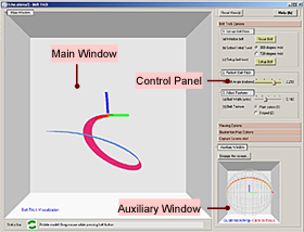
Interface: The application has a screen labeled 'Main Window', which shows the belt as a strip of elastic and flexible material. The 'Auxiliary Window' displays the quaternion-curve corresponding to frames along the length of belt.

The 'Control Panel' has the controls and options for the belt-trick application.

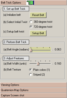
Try this: The application starts with the belt in the 360°-configuration, i.e. with a single twist. Perform the belt-trick by clicking and dragging the slider in the control panel located under tab: 'Belt Trick Options > 2. Perform Belt Trick > (a) Belt Angle (radians)'


Figure 1: Application interface

1. Performing the Belt-Trick -

Click to display the tab named 'Belt Trick Options' in the panel on the right side of the application window. Follow the steps below:

    • 1 - Set up Belt Trick

       
      • a) initialize the belt by clicking the button 'Reset Belt'
      • b) select the initial twist by pressing the radio-buttons '360-degree twist' or '720-degree twist'
      • c) twist the belt according to above selection (360º or 720º) by clicking the button 'Setup Belt'
         
    • 2 - Perform Belt Trick
       
      • a) deform the belt by moving the slider 'Belt Angle'. This slider changes the angle in the parametric
        equation describing the motion of the belt through space.

         
    • 3 - Adjust Features (optional)

       
      • a) adjust belt width by moving the slider 'Belt Width (units)'
      • b) select belt texture by pressing the radio-buttons 'Plain colors' or 'Strip
top


Figure 2: Tab to perform the belt-trick

2. Adjusting Viewing Options -

Click to display the tab named 'Viewing Options' in the panel on the right side of the application window.

    • 1 - Display Options: are used to show or hide belt features

       
      • click the check-boxes to turn on the corresponding options
      • corresponding keyboard short-cuts are shown as letters in brackets
      • various options are
        • Belt Face (f): choose to show or hide surface of belt
        • Belt Edges (e): choose to show or hide edges of belt-segments (helpful when there are more than one belts)
        • Axes (a): show or hide global co-ordinate axes
        • Belt Frames (Shift+f): choose to show or hide orientation-frames on belt-segments
        • Tracker (t): choose to show or hide orientation-frame tracker (more on tracker here)

           
    • 2 - Bounding Spheres: these options can be used to control the display for the spheres representing the space between end segments on the belt.

       
      • display or hide the spheres by clicking the checkbox 'Bounding Spheres' [or press key 'b']
      • choose the number of spheres by moving the slider 'No. of Spheres' (default = 3)

         
    • 3 - Multiple Belts: these options can be used to choose options for more than one belt.

       
      • choose the number of belts by moving the slider 'No. of Belts' (default = 1)
      • display or hide the belt numbers by clicking the checkbox 'Belt Numbers' [or press key 'n']
      • track a certain belt by selecting the belt-number in drop-down box 'Track Belt #' (default = none)
      • display only the belt being tracked by clicking the checkbox 'Hide all other Belts' [or press key 'o']

         
    • 4 - Quaternion Components: this option selects what quaternion components will be projected to three-dimensional space out of the four elements of a unit quaternion namely, (x, y, z, w). More on quaternion-curve display in this section below.
       
      • choose the quaternion component by pressing the appropriate radio-button:
        • 'Component XYZ' - select X, Y, and Z to project to three-dimensions
        • 'Component WYZ' - select W, Y, and Z to project to three-dimensions (default)
        • 'Component WXY' - select W, X, and Y To project to three-dimensions
        • 'Component WXZ' - select W, X, and Z to project to three-dimensions
top


Snapshot of the View-options tab
Figure 3: Tab to adjust viewing options

3. Quaternion-Curve display -

The quaternion-curve, or the quaternion-'map', is displayed in the 'Auxiliary Window' below the controls panel. The auxiliary-window displays the quaternion curve corresponding to the current state of the belt.

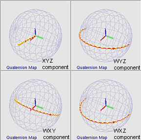
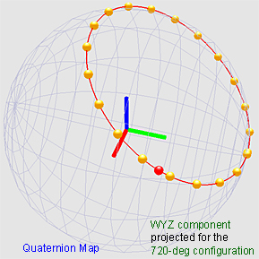
Recall that a quaternion-curve is obtained by connecting the quaternions that represent orientations of the belt-segments. Quaternion-curve for a 360° belt-configuration is an open curve (as shown in figure 4b and 4c). The figure-4d shows the quaternion-curve for 720° belt-configuration, which is a closed loop.
 

  • Maximize Auxiliary Window:
    • the auxiliary window can be maximized by clicking on the button 'Enlarge this screen'. This essentially swaps the contents of the main-window and auxiliary window. To restore, click on the button again.

      Figure-4a shows a view of the Auxiliary-Window.
       
  • What is a Quaternion Map: A visualization of quaternions corresponding to some orientation frames is called a quaternion-map. In our case, the quaternion-map is actually a curve in the quaternion-space.

    Since quaternions are four-dimensional vectors, a quaternion-map can be visualized only after projecting the four-dimensional quaternion-points into three-dimensional space. This is done by picking any three of the four components and rendering them as beads in a unit-sphere.

    Figure-4b shows the four possible projections of the quaternion-map corresponding to the quaternion-curve for orientations on a belt, which has been twisted once (360° configuration). Furthermore, the map corresponds to one of the stages in belt deformation, which happens to be the same as in figure-7 below.
     
  • Quaternion Tracker: All the quaternions that are displayed as small Yellow-beads correspond to the orientation of frames on the segments of the belt.

    The quaternion rendered as Red-bead corresponds to the orientation of the (frame) tracker. As the tracker is moved along the belt, the red-quaternion-bead changes its position, always remaining on the quaternion-curve, to correspond to the tracker's new orientation. 
     
  • Snapshots of Quaternion-Curve Deformations:

    a) Sequence of figures showing the quaternion-curve deformations for the 360° or double-twist configuration:-
     
    Formulation of quaternions: q(t, α) = [ cos(t, π), 0, sin(α)sin(t, π), cos(α)sin(t,π) ]


    α = 0.0 α = π/6 α = 2π/6 α = 3π/6 α = 4π/6 α = 5π/6 α = π

    b) Sequence of figures showing the quaternion-curve deformations for the 720° or double-twist configuration:-
     

    Formulation of quaternions: q(t, β) = [ sin2(β) + cos2(β)cos(2t, π), 0, cos(β)sin(β)(1 - cos(2tπ)), cos(β)sin(2tπ) ]

    β = 0.0 β = π/12 β = 2π/12 β = 3π/12 β = 4π/12 β = 5π/12 β = π/2

top


Figure 4a: View of Quaternion-curve (or map)

Snapshot of Quaternion-components
Figure 4b: Various quaternion-map components

Snapshot of Quaternion-map
Figure 4c: Quaternion map showing beads for orientation frames for tracker (left) and belt-segment orientation frames (right) for 360° configuration of the belt


Snapshot of Quaternion-map for 720-degree case
Figure 4d: Quaternion map showing the quaternion-curve for the 720° configuration of the belt

4. Multiple Belts options -
 

    • 1 - Multiple Belts: Once the belt-trick has been performed using a single belt, it is very interesting to see how more than one belts would behave during the trick.

      For this purpose, there is a provision to add additional belts to the mode. In the tab 'Viewing Options > 3. Multiple Belts' section, move the slider 'No. of Belts' to add more belts to the model.

      Once the multiple belts have been added, the belts can be set in the 360° or 720° configuration. The belt trick can then be performed by dragging the slider in the tab: 'Belt Trick Options > 2. Perform Belt Trick > Belt Angle (radians)'.

      It is observed that the all the belts deform without ever intersecting or touching each other. Currently, up to 14 belts can be made to undergo the transformations, though, any number of belts can be added.

      A view of three belts in the 360° configuration is shown in figure-5a.

       
    • 2 - Track Belt: In case of multiple belts, the deformation of a particular belt can be followed by highlighting or 'tracking' that belt.

      A belt can be tracked by selecting the sequence-number of the belt from the drop-down in the tab: 'Viewing Options > 3. Multiple Belts > Track Belt #'. Tracking a particular belt renders other belts in an edge-only mode. This makes it easier to follow how a particular belt deforms during the belt trick.

      Other belts can be hidden by pressing and selecting the checkbox in the tab: 'Viewing Options > 3. Multiple Belts > Show/Hide - Hide all other Belts (o)'.

      Figure-5b shows a specific belt as highlighted and other belts in edge-only mode.

top


View of Multiple-belts
Figure 5a: View of 3 belts twisted for the 360° configuration

View of Multiple-belts with a single belt highlighted
Figure 5b: Tracking a particular belt.


5. Bounding Spheres options -

    • Bounding Spheres: In order to visualize how the belt-segments sweep through the space, bounding-spheres can be turned on.

      This can be done in the tab:  'Viewing Options > 2. Bounding Spheres' section, by pressing and selecting the checkbox in the tab: 'Viewing Options > 2. Bounding Spheres > Show/Hide - Bounding Spheres (b)'.

      Up to 10 bounding spheres can be added and viewed before it becomes too dense to distinguish the spheres.

      Figure-6 shows 3 concentric spheres for the belt configuration shown in figure-5a. The belts are attached to the spheres at fixed positions and therefore as the belts move through space, they never intersect with one another.

top

View of Multiple-belts with Bounding-spheres
Figure 6: View of Bounding-spheres for the belt configuration in figure-5

6. Frame Tracker options -
 

    • Frame Tracker: A Frame-Tracker is a frame-triad, which can be moved and placed anywhere along the length of the belt. The purpose of the tracker is to follow the orientation of any segment of the belt during the deformation of the belt. 

      To adjust the tracker position, in the Main-Window, press and drag the middle-mouse button. The tracker can be enabled by the option in the tab:  'Viewing Options > 1. Display Options' section, by pressing and selecting the checkbox in the tab: 'Viewing Options > 1. Display Options > Tracker (t)'.

      Figure-7 shows the orientation of the Frame-Tracker as the belt is in one of the stages of deformation for the 360° configuration.

      The orientation of the tracker is rendered as a distinct quaternion in the quaternion-map display. Read the section on 'Quaternion-Tracker' linked here for more information.

top

View of Tracker on the belt
Figure 7: View showing the Frame-Tracker

7. Miscellaneous Options
 

    • Reset View:
       
      • reset the view of the belt model by clicking on the button 'Reset View' at the top of the controls panel [or press key 'r']

         
    • Help:
       
      • bring up this help page by clicking on the button 'Help' at the top of the controls panel [or press key 'h']
         
    • Capture Screen - Click to display the tab named 'Capture Screen' in the panel on the right side of the application window.

       
      • this option allows an image of the model of the belt to be saved as a .bmp file
      • images can be saved by clicking the button 'Save as BMP' in the panel
      • images will be saved in the folder "...<path to application folder>/snapshots/."
      • Note: images can be used freely along with due acknowledgement to this website.
         

top


Snapshot of Reset and Help buttons
Figure 8a: Reset and Help buttons


Figure 8b: View of tab to capture screen contents

V. Keyboard Shortcuts...

Global options
operation key
Quit ESCAPE
Help "h"
Reset View "r"
Swap Screens "q"
 
toggle feature key
Axes "a"
Bounding Spheres "b"
Central sphere "c"
Edges "e"
Faces "f"
Frames "Shift+f"
Belt Numbers "n"
Hide other belts "o"
Tracker on belt "t"
Belt Color options
operation key
Solid colors "1"
Striped pattern "2"
Quaternion Map options
operation key
Show component XYZ "w"
Show component WYZ "x"
Show component WXZ "y"
Show component WXY "z"

top


VI. Mouse Interface...

Operation Button + Action
Rotate Model Left + drag
Translate Tracker Middle + drag horizontally
Scale Model Right + drag vertically

top


Page Maintained by :
Sidharth Thakur
Graphics and Visualization Lab,
Computer Science Department, Indiana University Bloomington