Chapter 01
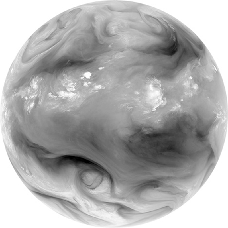
FIGURE 1.1 Infrared satellite image near a wavelength of 6.7µm, which is known as the "water vapor" channel since it captures the distribution of that field in a layer roughly 5 to 10 km above Earth's surface. Because water vapor is continuously distributed, in contrast to clouds, atmospheric motion is especially well captured. Here we see the convective clouds in the tropics and the mixing effects of eddies at higher latitude. (Source: NASA.)
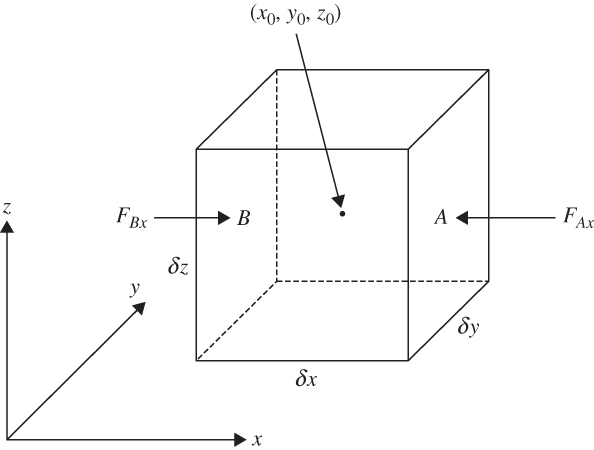
FIGURE 1.2 The x component of the pressure gradient force acting on a fluid element.
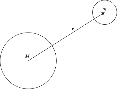
FIGURE 1.3 Two spherical masses whose centers are separated by a distance r.
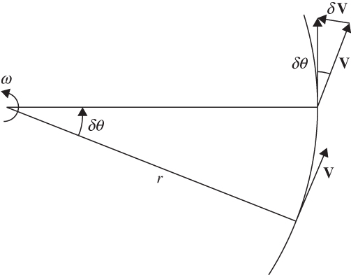
FIGURE 1.4 Centripetal acceleration is given by the rate of change of the direction of the velocity vector, which is directed toward the axis of rotation, as illustrated here by δV.
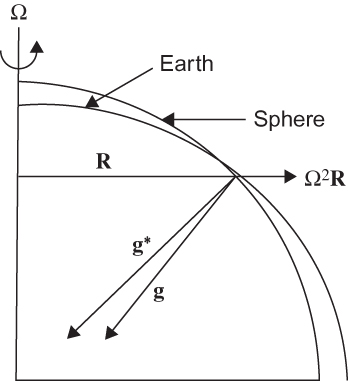
FIGURE 1.5 Relationship between the true gravitation vector g* and gravity g. For an idealized homogeneous spherical Earth, g* would be directed toward the center of Earth. In reality, g* does not point exactly to the center except at the equator and the poles. Gravity, g, is the vector sum of g* and the centrifugal force and is perpendicular to the level surface of Earth, which approximates an oblate spheroid.
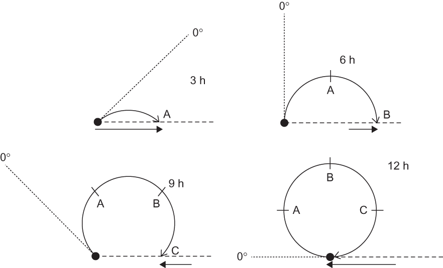
FIGURE 1.6 Motion of a frictionless object launched from the North Pole along the 0° longitude meridian at t = 0, as viewed in fixed and rotating reference frames at 3, 6, 9, and 12 h after launch. The horizontal dashed line marks the position that the 0° longitude meridian had at t = 0, and the short dashed lines show its position in the fixed reference frame at subsequent 3-h intervals. The horizontal arrows show 3-h displacement vectors as seen by an observer in the fixed reference frame. Heavy curved arrows show the trajectory of the object as viewed by an observer in the rotating system. Labels A, B, and C show the position of the object relative to the rotating coordinates at 3-h intervals. In the fixed coordinate frame, the object oscillates back and forth along a straight line under the influence of the restoring force provided by the horizontal component of gravitation. The period for a complete oscillation is 24 h (only 1/2 period is shown). To an observer in rotating coordinates, however, the motion appears to be at constant speed and describes a complete circle in a clockwise direction in 12 h.
FIGURE 1.7 For poleward motion, air parcels move closer to the axis of rotation and, through angular momentum conservation, the zonal wind accelerates.
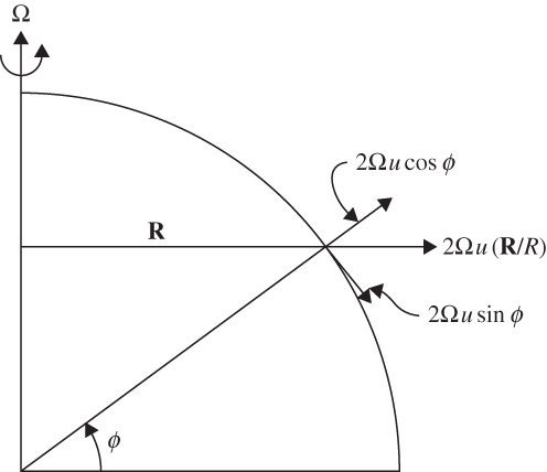
FIGURE 1.8 Components of the Coriolis force due to relative motion along a latitude circle.
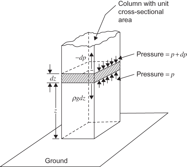
FIGURE 1.9 Balance of forces for hydrostatic equilibrium. Small arrows show the upward and downward forces exerted by air pressure on the air mass in the shaded block. The downward force exerted by gravity on the air in the block is given by ρgdz, whereas the net pressure force given by the difference between the upward force across the lower surface and the downward force across the upper surface is –dp. Note that dp is negative, as pressure decreases with height. (After Wallace and Hobbs, 2006.)
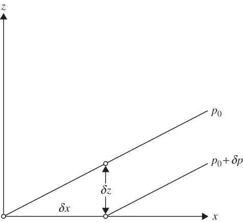
FIGURE 1.10 Slope of pressure surfaces in the x, z plane.
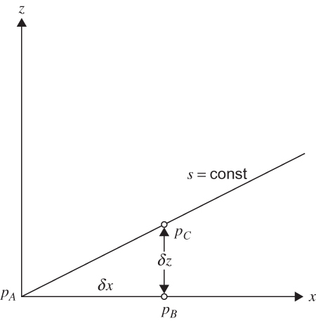
FIGURE 1.11 Transformation of the pressure gradient force to s coordinates
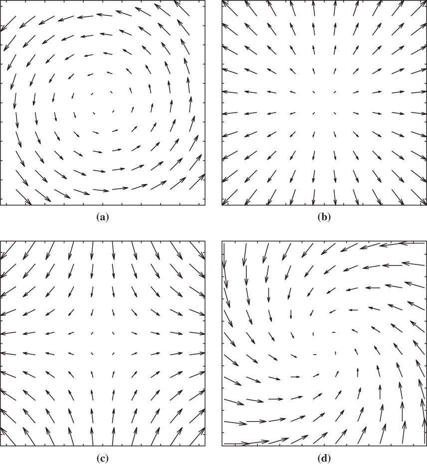
FIGURE 1.12 Velocity fields associated with pure vorticity (a), pure divergence (b), pure deformation (c), and a mixture of vorticity and convergence (d).